和英特許翻訳メモ

便利そうな表現、疑問、謎、その他メモ書き。思いつきで書いてます。
拾った用例は必ずしも典型例、模範例ではありません。

電極合剤

2024-05-05 21:58:31 | 英語特許散策

US8313866(TIAX LLC [US])
 The porosity was between 30 and 40%, translating to an electrode coating density of between 1.35 and 1.45 g/cc.
前記気孔度は、30から40%の範囲であり、これは、電極合剤の密度が1.35から1.45g/ccに該当する。

Lithium-ion anode half cells were built using 2016 size coin cell with the electrolyte formulations of EXAMPLES 9 and 10 as well as with COMP. EX. 1 to evaluate 1st cycle efficiency and to measure ac impedance (EIS) at −40° C.
リチウムイオン陰極半電池セルは、初期充放電効率の評価と-40℃での交流インピーダンス測定のために、実施例9と10及び比較例1の電解液組成物を用いて2016型コインセルから作られた。

AU2014405960(SOLVIONIC [FR])
and (S3) applying the electrode mixture powder to at least one surface of a current collector.
(S3)電極合剤粉末を集電体の少なくとも一面に塗布するステップ  

US2021265636(UNIV STUTTGART [DE])
[0012] A further electrode for a secondary battery is disclosed in WO 2018/048166 A1.
【0012】
特許文献2には別の二次電池用電極が開示されている。

The electrode is produced by introducing an electrode mixture containing an active electrode material into pores of a current collector having a three-dimensional network structure.
該電極は、三次元ネットワーク構造を有する集電体の孔に電極活性物質を含む電極合剤を導入することにより製造される。

As an example for this three-dimensional structure, conductive metal felts are mentioned in WO 2018/048166 A1 as suitable for use in flexible batteries.
この三次元構造の例として、特許文献2にはフレキシブル電池での使用に好適なものとして導電性金属フェルトが挙げられている。

US2022109182(MITSUI MINING & SMELTING CO LTD [JP])
[0002] The present invention relates to a sulfide solid electrolyte.
【0001】
  本発明は硫化物固体電解質に関する。

Also, the present invention relates to an electrode mixture and a solid-state battery that contain the sulfide solid electrolyte.
また本発明は、該硫化物固体電解質を有する電極合剤及び固体電池に関する。

Furthermore, the present invention relates to a method for producing the sulfide solid electrolyte.
更に本発明は、該硫化物固体電解質の製造方法に関する。

EP3975285(KUREHA CORP [JP])
However, it is known that a positive electrode mix containing an active material having a high nickel proportion has problems in that the viscosity of the electrode mix in a slurry form tends to be increased during storage and the electrode mix may be gelled in some cases.
しかし、ニッケル比率の高い活物質を含む正極合剤には、スラリー状である電極合剤の粘度が保管中に高まりやすく、場合によってはゲル化してしまうことがある、という問題があることが知られている。

Hereinafter, in the present application, an active material having a nickel proportion of 55 mol% or greater is referred to as a high-nickel active material.
以下、本願ではニッケル比率55mol%以上の活物質をハイニッケル系活物質と呼ぶこととする。

US2022081309(SUMITOMO CHEMICAL CO [JP])
[0100] Examples of a method of suitably producing such a nonaqueous electrolyte secondary battery include
【0064】
  このような非水電解液二次電池を好適に製造する方法としては、

a method including: applying an alumina slurry to a surface of a positive electrode and/or a negative electrode which include an electrode mix layer containing an electrode active material (positive electrode active material or negative electrode active material) and a binder;
電極活物質(正極活物質又は負極活物質)とバインダーとを含む電極合剤層を含む正極及び/又は負極の表面にアルミナスラリーを塗工する工程と、

and drying the alumina slurry to form an alumina film. 
アルミナスラリーを乾燥してアルミナ膜を形成する工程とを含む方法が挙げられる。

EP3806208(MAXELL HOLDINGS LTD [JP])
[0063] FIG. 2 shows a horizontal cross-sectional view of the cylindrical non-aqueous electrolyte primary battery in FIG. 1 .
【0064】
  図2には、図1の筒形非水電解液一次電池の横断面図を示している。

As shown in FIG. 2 , the wound electrode body 3 is obtained by winding a long positive electrode 4 and a long negative electrode 5 with the separator 6 interposed therebetween substantially in the form of a cylinder as a whole. 
図2に示すように、巻回電極体3は、長尺の正極4と長尺の負極5とを、セパレータ6を介して巻回してなるものであり、全体として略円柱形状に形成されている。

 In the cylindrical non-aqueous electrolyte primary battery 1 of FIG. 2 , the positive electrode 4 has a structure in which two positive electrode mixture sheets 41, 42 are stacked with a current collector 43 interposed therebetween.
図2に示す筒形非水電解液一次電池1では、正極4は、2枚の正極合剤シート41、42が、集電体43を介して積層された構造を有している。

コメント
  • X
  • Facebookでシェアする
  • はてなブックマークに追加する
  • LINEでシェアする

窪み、くぼみ

2024-05-05 21:46:51 | 英語特許散策

WO2016014365(MEDTRONIC MINIMED INC [US])
[0555] In particular embodiments, the engagement portion 80 on the cap 4 (or the base/reservoir/cap unit) has a feature (a protrusion, bump, extension, depression or the like) having the contact surface that engages the second end 78 of the moveable member 70,

when the cap 4 (or the base/reservoir/cap unit) is in a fully and properly inserted position within the reservoir receptacle 32. 
[0457] 特定の実施形態では、キャップ4(又は基部/リザーバ/キャップユニット)がリザーバ受容部32内の十分にかつ適切に挿入された位置にあるとき、

キャップ4(又は基部/リザーバ/キャップユニット)上の係合部分80は、可動部材70の第2の端部78と係合する接触面を有する特徴部(突出部、凸部、延出部、窪部など)を有する。

US9371153(MODERN TWIST INC [US])
[0043] In some embodiments, the shapes and dimensions of the press-fit elements may also contribute significantly to the leak resistance of the seal. 
【0031】
  いくつかの実施形態では、圧入部の形状および寸法も、封止部の防漏性に大きく寄与するかもしれない。

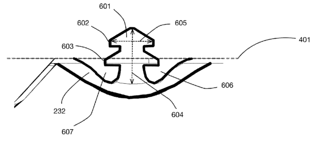
FIG. 6 illustrates details of the bottom-press fit element 232 of the embodiment shown in FIG. 5.
図6は、図5に示された実施形態の底側圧入部232を、詳細に示している。

In this embodiment, vertical protrusion 601 extends upward from the bottom press-fit element, while cavities 606 and 607 are on either side of this vertical protrusion. 
本実施形態において、垂直突出部601が、底側圧入部から上方に延伸し、窪み部606、607が、この垂直突出部の両側にある。

US11572301(SCHOTT AG [DE])
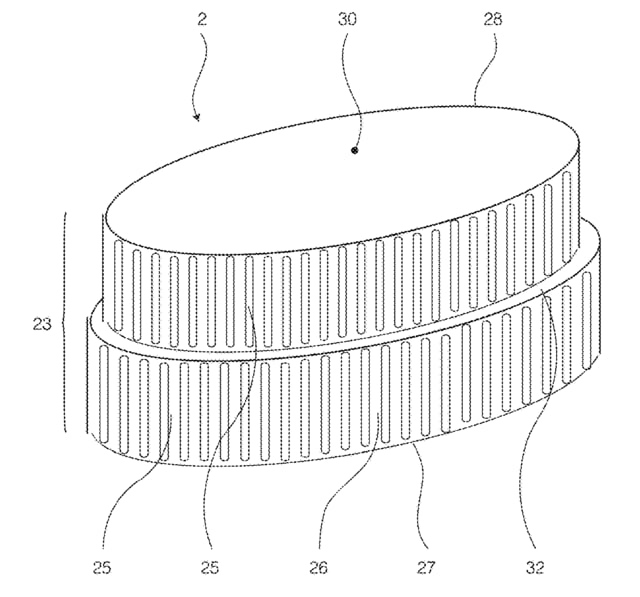
[0154] FIG. 11 a shows a sheet glass element according to the invention, which is distinguished by
【0138】
  図11aに示す本発明の面状のガラス部材2が特徴とする点は、

an edge surface 25 having adjacently aligned filamentary damages 26 forming indentations in the edge surface 25 ,
エッジ面25において並んで延在する複数の線条状の傷26が設けられており、これらの線条状の傷26はエッジ面25の窪部を成し、

wherein a longitudinal extension of the filamentary damages 26 extends in the direction from one edge 27 to the other edge 28 , which edges define the transition between the edge surface 25 and the faces 30 of sheet glass element ,
線条状の傷26の長手方向は、当該面状のガラス部材2の各面30とエッジ面25との間の移行部となる一方のエッジ27から他方のエッジ28へ向かう方向に延在し、

and wherein the edge surface 25 has an offset 32 extending along the entire edge surface 25 and extending substantially perpendicular to the longitudinal extension of the filamentary damages 26 
エッジ面25は、当該エッジ面25全体に沿って延在するオフセット32を有し、当該オフセットは、線条状の傷26の長手方向に対して実質的に垂直に延在することである。

US11428231(BORGWARNER INC [US])
[0007] The grooves are in particular in the form of pockets. That is to say the grooves are not apertures in the wall of the bearing housing but rather are pockets or indentations or recesses.
【0007】
  溝は、特にポケットの形態である。すなわち、溝は、軸受ハウジングの壁部のアパーチュアではなく、むしろポケット又は窪部又は凹部である。

コメント
  • X
  • Facebookでシェアする
  • はてなブックマークに追加する
  • LINEでシェアする

信号を通過させる

2024-05-05 12:31:57 | 英語特許散策

US11610573(SILENCER DEVICES LLC [US])
[0144] The Offline Signal Processing system can be implemented as illustrated in FIG. and described above.
オフライン信号処理システムは、図3に示して上述したように実現することができる。

In this embodiment, known noise characteristics can be reduced or eliminated from recordings, or in a live situation with an appropriate delay between the action and actual broadcast.
この実施形態では、レコーディングから、あるいは行動と実際の放送との間に適切な遅延を伴うライブの状況において、既知のノイズ特性を低減または除去することができる。

In this embodiment, the Core Engine may be a “plug in” of another editing or processing software system, incorporated into another signal processor, or as a stand-alone device as shown in FIG. 20 .
この実施形態では、コアエンジンは、別の信号プロセッサに組み込まれた別の編集または処理ソフトウェアシステムの「プラグイン」であってもよいし、図20に示すようなスタンドアロンの装置であってもよい。

If the characteristics of the noise to be removed
仮に除去対象となるノイズの特性

(or alternatively, of the signal to be passed in an unknown noise environment: excluding those frequencies from the frequency band range settings and setting the amplitude scaling factor to 1 for frequencies not included in the frequency band range definitions would enable only those frequencies to pass),
(あるいは、未知のノイズ環境で通過対象となる信号の:周波数帯域範囲の設定からそれらの周波数を除外し、周波数帯域範囲の定義に含まれていない周波数の振幅スケーリング係数を1に設定することが、それらの周波数だけを通過させられる)、

the system parameters can be set manually (or via presets) to effectively remove the noise and pass the target signal
ノイズを効果的に除去し、ターゲット信号を通過させるためにシステムパラメーターを手動で(またはプリセットを介して)設定することができる。

GB2609539(SKYWORKS SOLUTIONS INC [US])
[0073] The band stop filters of Figures 1A, 1B, and 1C, can provide a stop band in a larger pass band of a band pass filter, a low pass filter, or a high pass filter.
【0047】
  図1A、図1B及び図1Cの帯域阻止フィルタは、帯域通過フィルタ、低域通過フィルタ又は高域通過フィルタの大きな通過帯域に阻止帯域を与えることができる。

As one example, the band stop filters of Figures 1A, 1B, and 1C can provide a 2.4 GHz Wi-Fi stop band in a band pass filter for passing MHB signals.
一例として、図1A、図1B及び図1Cの帯域阻止フィルタは、MHB信号を通過させための帯域通過フィルタに2.4GHzWiFi阻止帯域を与えることができる。

EP4214646(IBM [US])
[0008] In an embodiment, the radio frequency multiplexer includes a plurality of bandpass filters
【0008】
  ある実施形態において、前記無線周波数マルチプレクサは、複数のバンドパスフィルタを含み、

each allowing a corresponding one recovered qubit control signal to pass
前記複数のバンドパスフィルタはそれぞれ、対応する1つの回復されたキュビット制御信号を通過させ

while attenuating or substantially blocking all other recovered qubit control signals.
一方で、全ての他の回復されたキュビット制御信号を減衰させる又は実質的にブロックする。

In an embodiment, the demodulator includes a direct optical to electrical converter.
ある実施形態において、前記復調器は、直接光/電気変換器を含む。

US11415646(BOEING CO [US])
The method proposed herein promises to be scalable and low cost. That method uses a single sensor that can reconstruct individual pixels through association with a known pseudo-random pattern determined by a compressive sensing algorithm.
本法方では、圧縮センシングアルゴリズムによって決定される既知の疑似ランダムパターンと関連づけることにより、単一のセンサを使用して個々のピクセルを再構築することができる。

Each pixel captures a portion of the total image.
各ピクセルは、全体の画像の一部を構成する。

The system attempts to “null” the magnetic field at various pixel locations (effectively creating a digital 0)
本システムでは、様々なピクセル位置において磁場を「ヌル化(null)」し(実質的に、デジタル値0を生成し)、

and letting the signal come through the pixel (this is effectively a digital 1).
このピクセルに信号を通過させ(実質的にデジタル値1に相当)ようにする。

This allows for image generation by rastering through the pixel array.
これにより、ピクセルアレイをラスタリング(rastering)して、画像を生成することが可能になる。

US11936509(ERICSSON TELEFON AB L M [SE])
[0008] Since an OOK signal is a signal modulated only in amplitude and not in frequency its detection is almost independent of frequency accuracy and phase noise.
【0007】
  OOK信号は、振幅においてのみ変調され、周波数において変調されない信号であるので、それの検出は、周波数精度および位相ノイズとほとんど無関係である。

This means that a receiver may employ a frequency down-conversion with a free-running oscillator whose frequency is not locked, so that intermediate frequency (IF) becomes uncertain.
これは、受信機が、それの周波数がロックされない自励(free-running)発振器を用いた周波数ダウンコンバージョンを採用し得、その結果、中間周波数(IF)が不確定になることを意味する。

A simple analog amplitude detector may be used to demodulate an OOK signal at the uncertain IF.
不確定なIFにおいてOOK信号を復調するために簡単なアナログ振幅検出器が使用され得る。

The amplitude detector is to be surrounded by filters,
振幅検出器はフィルタによって囲まれるべきであり、

one on the input side to let through the signals within IF frequency range in which the desired signal may reside,
入力側のフィルタは、所望の信号が常駐し得るIF周波数範囲内で信号を通過させためのものであり、

and one at the output to attenuate amplitude variations of the signal with higher frequencies than those corresponding to the OOK. 
出力のフィルタは、OOKに対応する周波数より高い周波数を用いて信号の振幅変動を減衰させるためのものである。

コメント
  • X
  • Facebookでシェアする
  • はてなブックマークに追加する
  • LINEでシェアする

非可逆

2024-05-05 11:59:16 | 英語特許散策

WO2018213200(OUSTER INC [US])
In some embodiments, optical components 1 16 can also be a part of the monolithic structure in which sensor array 108, processor 1 18, and memory 120 are a part.
いくつかの実施形態では、光学部品116は、センサアレイ108、プロセッサ118、及びメモリ120が一部であるモノリシック構造の一部とすることもできる。

In such instances, optical components 116 can be formed, e.g., bonded (non-reversibly) with epoxy, on the ASIC so that it becomes part of the monolithic structure, as will be discussed further below. 
そのような場合、以下で更に説明するように、光学部品116を形成することができ、例えば、ASIC上でエポキシで(非可逆的に)接合し、ASICをモノリシック構造の一部とすることができる。

US11523460(NOKIA TECHNOLOGIES OY [FI])
Intra-frame coding may use lossy coding techniques that require only the information carried in the compressed frame for decoding.
フレーム内符号化は、復号化のために圧縮フレームで搬送される情報のみを必要とする非可逆符号化技術を使用することができる。

In contrast, inter-frame coding applies differential techniques across multiple frames to encode and transmits only the differences across consecutive frames.
対照的に、フレーム間符号化は、複数のフレームにわたる差分技術を適用して符号化し、連続するフレーム間の差分のみを伝送する。

US11677128(RAYTHEON CO [US])
[0029] The non-reciprocal circulator 102 includes any suitable structure configured to allow RF signals to circulate between different inputs and outputs in a non-reciprocal manner.
【0017】
  [0022]  非可逆サーキュレータ102は、RF信号が、異なる入力と出力の間を非可逆的な方法で循環できるように構成された適切な任意の構造を含む。

The phrase “non-reciprocal” indicates that forward and reverse signals (meaning incoming and outgoing signals) at the same port traverse different paths,
語句“非可逆的(non-reciprocal)”は、同じポートにおけるフォワード信号とリバース信号(入信号と出信号を意味する)が異なる経路を進行することを示し、

which helps to permit movement of the signals in a clockwise or counter-clockwise direction (but not both).
これは、時計回り又は反時計回り方向(但し、両方ではない)で信号の進行を可能にすることを支援する。

In some embodiments, the non-reciprocal circulator 102 represents a field effect transistor (FET) or other transistor-based non-reciprocal circulator. 
幾つかの実施態様において、非可逆サーキュレータ102は、電界効果トランジスタ(FET)又はその他のトランジスタに基づく非可逆サーキュレータを表す。

US9935351(SKYWORKS SOLUTIONS INC [US])
[0086] As mentioned above, isolator and circulator junctions are commonly used in conjunction with microwave and/or radio frequency signaling, though they can be used in other applications as well.
【0055】
  上述したように、アイソレーターおよびサーキュレータージャンクションは、他の設備にも使用することができるが、一般的にマイクロ波および/または高周波信号伝達と併せて使用される。

Typically, the junctions are passive, non-reciprocal three or four port devices, though the particular number of ports is not limiting. 
典型的には、ジャンクションは、3つまたは4つの非可逆ポートを有する受動装置である。ポートの数は、特に制限されていない。

FIG. 21 illustrates a basic example of such a junction having ports , and .
図21は、ポート1、ポート2およびポート3を有するジャンクションの基本例を示している。

These ports are points in which an external waveguide or transmission line connects to the device, such as discussed with respect to FIG. 16A above.
これらのポートは、上記の図16Aを参照して説明したように、外部導波路または伝送線路が装置と接続する点である。

In some embodiments, when a signal enters into one of the ports, in either a circulator or an isolator, the signal is directed to output at an adjacent port.
いくつかの実施形態において、信号がサーキュレーターまたはアイソレーターのポートのいずれか1つに入射した場合、この信号は、隣接するポートから出射するように案内される。

コメント
  • X
  • Facebookでシェアする
  • はてなブックマークに追加する
  • LINEでシェアする

複数の偏光

2024-05-05 11:34:52 | 英語特許散策

US2021184110(QUANTUM VALLEY IDEAS LABORATORIES [CA])
[0032] In some aspects of what is disclosed herein, a radar system includes a receiver station having one or more photonic crystal receivers for receiving signals of radio frequency (RF) electromagnetic radiation.
【0007】
  本明細書に開示するいくつかの態様では、レーダシステムは、無線周波(RF)電磁放射の信号を受信するための1つまたは複数のフォトニック結晶受信器を有する受信ステーションを含む。

The radar system may be a multi-static radar system or other type of radar system. The photonic crystal receivers can be formed of dielectric material, and as such, may be grouped or clustered.
レーダシステムは、マルチスタティックレーダシステムまたは他のタイプのレーダシステムとすることができる。フォトニック結晶受信器は、誘電性材料から形成することができ、したがってグループ化またはクラスタ化することができる。

When grouped or clustered, the photonic crystal receivers can minimally interfere with each other and allow the radar system to operate with multifunctional capability.

For example, two or more photonic crystal receivers may be configured to filter different, respective polarizations (e.g., orthogonal polarizations].
たとえば、異なるそれぞれの偏光(たとえば、直交偏光)をフィルタリングするように、2つ以上のフォトニック結晶受信器を構成することができる。

Such configuration allows multiple polarizations to be determined at the same time and at approximately the same point in space. 
そのような構成により、複数の偏光空間内のほぼ同じ点で同時に判定することが可能になる。

US10871457(HONEYWELL INT INC [US])
[0080] Radar array 312 , which is an example of transceiver circuitry 140 and 240 , includes circuit boards 326 A and 326 B.
【0074】
  送受信機回路140及び240の一例であるレーダアレイ312は、回路基板326A及び326Bを含む。

Radar array also includes transmit circuitry including array 318 , which can be patch elements integrated into PCB 326 A, and receive circuitry including array 320 , which can be patch elements integrated into PCB 326 B.
レーダアレイはまた、PCB326Aに一体化されたパッチ要素であり得るアレイ318と、PCB326Bに組み込まれたパッチ要素であり得るアレイ320を含む受信回路と、を含む送信回路を含む。

Array 320 may be configured to receive reflected radar signals having multiple polarization types.
アレイ320は、複数の偏光タイプを有する反射レーダ信号を受信するように構成することができる。

In some examples, array 320 may be able to simultaneously receive multiple polarizations, or array 320 may be configured to only receive one polarization at a time, which requires simpler circuitry.
いくつかの実施例では、アレイ320は、複数の偏光同時に受信することが可能であってもよく、又はアレイ320は、一度に1つの偏光のみを受信するように構成されてもよく、これは、より単純な回路を必要とする。

The processing circuitry can interleave operating modes, where each operating mode processes one polarization at a time.
処理回路は、操作モードを交互配置することができ、各操作モードは、一度に1つの偏光を処理する。

コメント
  • X
  • Facebookでシェアする
  • はてなブックマークに追加する
  • LINEでシェアする

受光画素

2024-05-05 11:14:17 | 英語特許散策

US11567175(INFINEON TECHNOLOGIES AG [DE])
[0026] The reflections of the emitted light beams are received by a photodetector 160 .
【0023】
  放射された光ビームの反射は、光検出器160によって受信される。

The photodetector 160 comprises a plurality of photosensitive elements arranged in at least one row, i.e. one or more parallel rows of photosensitive elements (which may be understood as an array of photosensitive elements).
光検出器160は、少なくとも1行に配置される複数の受光素子、すなわち、1つまたは複数の平行な行の受光素子を備える(受光素子のアレイとして理解されてもよい)。

Each of the plurality of photosensitive elements is configured to receive a reflection of at least one of the plurality of light beams from an object in the environment. 
複数の受光素子の各々は、環境内の物体からの複数の光ビームの少なくとも1つの反射を受信するように構成される。

 For example, the photodetector 160 may be a one-dimensional or a two-dimensional array of photosensitive pixels. 
例えば、光検出器160は、1次元または2次元アレイの受光画素でもよい。

US8513588(DOLBY LAB LICENSING CORP [US])
[0019] The chip measures light intensity at a number of pixel locations.
【0015】
  チップは、多数の画素位置で光の強度を測定する。

Values representing the intensity at each of the pixels can be read out and stored in a memory.
個々の画素における強度を表す値は、読出されてメモリに記憶できる。

Light sensitive chips also typically include means for selecting the amount of time the light sensitive elements collect light before the data stored therein is read out.
受光チップは、典型的に、データが記憶されて読出される前に、受光要素が光を集める時間の総量を選択する選択手段を含む。

Such means can act as an “electronic shutter”.
このような選択手段は、「電子シャッタ」として働くことができる。

For example, many CCD chips include a control that triggers reading out of pixel data from light-sensitive pixels into vertical data registers that are shielded from light.
たとえば多数のCCDチップは、受光画素から、画素データを垂直データレジスタに読出すことをトリガするトリガ制御を含む。

The inventors have determined that providing an electronic camera with multiple CCD chips allows the camera to capture multiple exposures of a single image simultaneously.
発明者は、カメラが単一の画像の多重露出(multiple exposure)を同時に把捉できるようにする、多数のCCDチップを有する電子カメラを提供することに決定した。

US9854214(RED COM INC [US])
[0019] In some implementations, the optical engine module is further
【0017】
  いくつかの実施態様では、光学エンジンモジュールはさらに、

configured to modulate light received from the light engine module based on the video data provided by the video processing module,
ビデオ処理モジュールによって供給されたビデオデータに基づいてライトエンジンモジュールから受光した光を変調し、

reduce a size(*不定冠詞)of received pixel(*違和感)s,
受光画素サイズを縮小し、

and move reduced size pixels within a bounded output pixel to at least 2 locations,
有界出力画素範囲内の縮小画素を少なくとも2カ所の位置に移動させるように構成され、

wherein the reduced size pixels are moved to the at least 2 locations at a rate that is at least 2 times faster than a frame rate of the video data.
縮小画素は、ビデオデータのフレームレートの少なくとも2倍の速さで少なくとも2カ所の位置に移動される。

US9006994(OSRAM SYLVANIA INC [US])
[0005] In one example, such a system may include a light source, such as one or more light emitting diodes (LEDs), configured to transmit modulated infrared light (IR), i.e. IR light that is rapidly turned on and off.
1実施例ではそれらシステムには、変調赤外光(IR)、即ち、高速点滅する赤外光を送る構成を有する1つ以上の発光ダイオード(LED)等の光源が含まれ得る。

The detector may receive the reflected light and calculate the phase shift imparted by reflection of the light back to the sensor.
検出器は反射光を受け、光の反射による位相シフトを算出する。

The time of flight of the received light may be calculated from the phase shift and distance to various points in the sensor field of view may be calculated by multiplying the time of flight and the velocity of the signal in the transmission medium.
算出した位相シフトから光を受けるまでの時間を算出し得、算出した前記時間を伝送媒体内における信号速度に乗算し、センサ視野内の種々の位置までの距離を算出し得る。

By providing an array of receiving pixels in the detector, the distance signals associated with light received at each pixel may be mapped to generate a three-dimensional electronic image of the field of view.
検出器内に受光画素列を設けることで、各画素位置で受けた光に関する距離信号をマッピングして視野の3次元電子イメージを生成させ得る。

WO2008058847(IBM [US])
Thus, according to one aspect of the invention, there is provided a CMOS imager sensor array and method of fabrication.
【0014】
  従って、本発明の1つの態様によれば、CMOSイメージャ・センサ・アレイ及び製造方法が提供される。

The CMOS imager sensor array comprises:
CMOSイメージャ・センサ・アレイは、

a substrate; an array of light receiving pixel structures formed above the substrate, the array having formed therein "m" levels of conductive structures, each level formed in a corresponding interlevel dielectric material layer;
基板と、基板上に形成された受光画素構造体のアレイであって、アレイがその中に形成された「m」レベルの導電性構造体を有し、各レベルが対応する層間誘電体材料層内に形成される、アレイと、

and, a dense logic wiring region formed adjacent to the array of light receiving pixel structures having "n" levels of conductive structures, each level formed in a corresponding interlevel dielectric material layer, where n>m.
受光画素構造体のアレイに隣接して形成され、「n」レベルの導電性構造体を有する高密度論理配線領域であって、各レベルが対応する層間誘電体材料層内に形成され、n>mである、高密度論理配線領域とを含む。

コメント
  • X
  • Facebookでシェアする
  • はてなブックマークに追加する
  • LINEでシェアする

当ブログの例文について

本ブログの「特許英語散策」等題した部分では、英語の例文を管理人の独断と偏見で収集し、適宜訳文・訳語を記載しています。 訳文等は原則として対応日本語公報をそのまま写したものです。私個人のコメント部分は(大抵)”*”を付しています。 訳語は多数の翻訳者の長年の努力の結晶ですが、誤訳、転記ミスもあると思いますのでご注意ください。