


Namuru-Nanoもそれなりに動いているので,しばらく放置していた
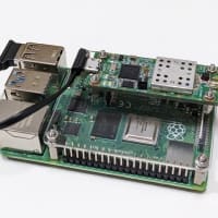
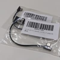
MAX2769基板に,オプティマイズのカメレオンUSB FX2を接続して
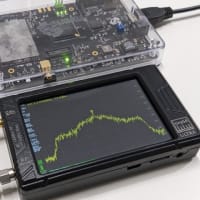
動作試験をしてみました.

結果は大惨事…
中心周波数付近の減衰がひどくて,GPS信号がまったく捕捉できません.

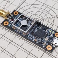
どうもRF信号ラインが細すぎて,インピーダンスがまったく合っていない
ようです.予算をケチって2層基板なので,ラインの幅は1mmは必要らしい.
0.4mmでは,ぜんぜん足りない.
 (クリックで拡大)
他にも,ANTBIASとSMAコネクタの間にキャパシタが入っているため,
LNAに給電できなかったり,ローパスフィルタ用のキャパシタの値が
推奨値の10分の1しかなかったりと,gdgdでした.
やっぱり勢いだけで設計するとろくなことがないな.
MAX2769基板に,オプティマイズのカメレオンUSB FX2を接続して
動作試験をしてみました.
結果は大惨事…
中心周波数付近の減衰がひどくて,GPS信号がまったく捕捉できません.
どうもRF信号ラインが細すぎて,インピーダンスがまったく合っていない
ようです.予算をケチって2層基板なので,ラインの幅は1mmは必要らしい.
0.4mmでは,ぜんぜん足りない.
 (クリックで拡大)
他にも,ANTBIASとSMAコネクタの間にキャパシタが入っているため,
LNAに給電できなかったり,ローパスフィルタ用のキャパシタの値が
推奨値の10分の1しかなかったりと,gdgdでした.
やっぱり勢いだけで設計するとろくなことがないな.


May be some max2769 settings are incorrect? I can check your settings on my board if you wish.
It is also a good idea to turn max2769 output in analog mode and to check it with spectrum analyzer.
I also noticed C36 blocked off the ANTBIAS from the antenna LNA. This is exactly what MAXIM does. I have no idea why they put this capacitor in the first place.
Two 100pF capacitors, C48 and C67, on LNAOUT line provide ten times more attenuation than that suggested by the datasheet.
Again, these are exactly the ones that used on the MAXIM evaluation kit :(
And I still don't think that the spectrum looks so strange because of impedance mismatch. It's interesting to see how spectrum will look like with antenna connected to the board. And to see what settings are used for max2769 (Or you don't use spi interface for max2769 configuring and use one of the preconfigured device state?)
BTW Some of Michele Bavaro's boards also contain max2769 on 2-layer pcb.
The device was used in a preconfigured state. I chose a 2-bit ADC with 16.368MHz sampling frequency.
I can send one for you if you are interested in messing it :)